 Goal
Goal
To enhance the understanding, discover new phenomena, and explore potential applications fiber optical trapping system.
Why Fiber Optical Tweezers
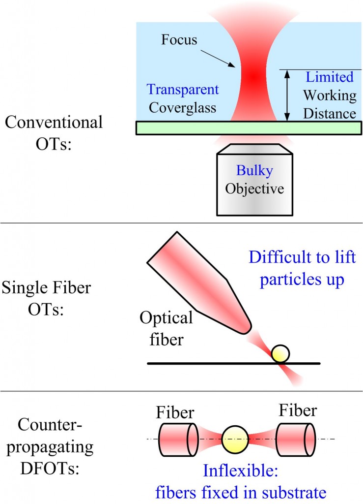
- Conventional optical tweezers (OTs) require an high NA objective lens to build up the trap(s), which is bulky, expensive, and have many restrictions such as working distances and compatible substrates.
- Fiber optical tweezers have small footprints, are integratable, and can flexibly move anywhere inside the medium. The system works as a miniature “probe”, compared with conventional optical tweezers as a large “platform”.
- Fiber optical tweezers don’t have any requirements on the substrate materials or thickness.
Why is our research important
- Common fiber based optical trapping systems, namely single-fiber OTs and counter-propagating OTs, suffer from diffiiculty of creating 3D traps and poor flexibility, respectively.
- The inclined DFOTs [1], which have a flexible system setup and readily achievable 3D trapping capability, have not been systematically studied before. We carried out the first experimental calibration of the optical forces in this system, enabling it to measure forces.
- Multiple functionalities were achieved with the DFOTs for the first time, making it potential for parallel manipulation and interaction force investigation.
- Fiber optical tweezers suffer from weak focusing of the light and hence low trapping efficiency, which is a majoy drawback compared with conventional optical tweezers. We achieved superfocusing on the fiber tip and a trapping efficiency comparable with that of conventional optical tweezers, without using a high-NA objective lens.
System 1: Dual Fiber Optical Tweezers
How does it work
- A
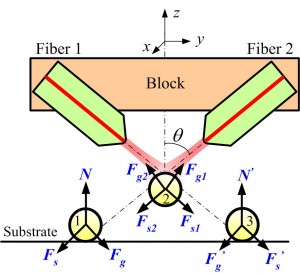 stable 3D trap (Bead 2) is enabled by balancing four force components (two scattering and two gradient) without the requirement of strong focusing.
 - Two 2D traps (1 and 3), are enabled by individual weakly focused optical beams.
- The separation of the traps can be tuned by changing the height of the block, enabling novel and promising functionalities.
What was achieved
1. Investigation of the 3D trap [2]
- Experimental calibration of the 3D trap was carried out with two methods: drag force method and power spectrum analysis.
- The parametric study of the 3D trap was studied based on our modeling. The simulation results match with those obtained in the experiments.
- Simulations reveal that the inclined DFOTs are more robust to the fiber misalignment when compared with the counter-propagating DFOTs.
2. Discovery of multiple traps and functionalities [3]
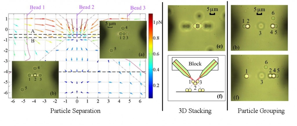 Multiple traps are discovered in experiments and studied both experimentally and numerically.
- Multiple functionalities, including bead separation, bead grouping, and bead stacking both in 2D and 3D, were demonstrated in the experiment.
- The functionalities was understood with our modeling results of the optical force field.

3. Manipulation of micro-rods [4]
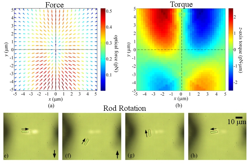 Compared with beads, micro-rods provide additional degrees of freedom to control, and hence more functionalities are achievable with the inclined DFOTs.
- Rod trapping, alignment, stacking, rotation, and binding were experimentally demonstrated.
- Modeling of the optical force and torque fields improves the understanding of these functionalities and help design the system to obtain desired ones.
So what?
- Flexibility and integrability: the inclined DFOTs can be used as a system block and can be readily integrated, which enables it to find new applications in Lab-on-a-chip systems.
- Capability as a force sensor: trapping stiffness was obtained in the experiments, for the first time, which enables the inclined DFOTs to be used in force sensing in addition to particle manipulation.
- System design based on specific requirements. The enhanced understanding of the inclined DFOTs provides suggestions on how to design the system to better fulfill the desired functions.
- Manipulation of irregularly shaped particles: the multiple traps facilitate complex functionalities to be realized with both spherical and cylindrical particles in on-chip systems.
- Distributed force applied on the cell membrane: possible for cell mechanical property measurement by stretching the cell without physical contact.
System 2: Fiber Based Surface Plasmonic Lens
How does it work
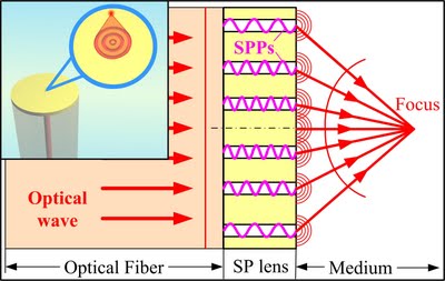
- The SP lens, fabricated directly on a fiber endface, is composed of a set of nanoscale concentric slits.
- The superfocusing is achieve by converting the planar wave front (in optical fiber) to a spherical one (in the medium).
- The concentric slits serves as waveguides of the surface plasmon polaritons (SPPs) that introduce desired phase delays to the SPPs propagating inside.
What was achieved
1. Experimental intensity profile demonstrating superfocusing on top of regular single-mode optical fibers. [5]
- Two SP lenses, one 3-ring and one 4-ring, were fabricated on fiber tips and tested.
- The spot sizes (FWHM’s) of both samples reach the diffraction limit of 0.51*wavelength / NA at the wavelength of 808 nm.
- The 3-ring SP lens achieved a focal size comparable with that of a high NA objective lens (~330 nm for NA=1.25).
- The transmission of the optical power is over 70% (normalized to the power incident on the slit openings) for both samples.


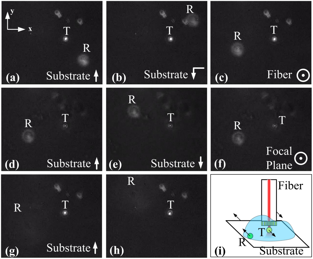
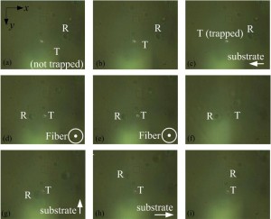
2. 3D trapping of sub-micron-size particles. [6]
- As one of the potential applications of the fiber-based SP lens, we have achieved 3D trapping of a 500-nm fluorescent polystyrene bead (in the lower left figure) and a sub-micron-size bacterium (in the lower right figure).
- “R” and “T” in the figures below designate reference particles (fixed to the substrate) and trapped particles (moving with the fiber), respectively. The text and arrows in the lower right corner of each picture specify the object to move and the direction to move along in the next step.
- The 3D trapping was achieved with a power of ~1 mW out of optical fiber, which is much lower than those used by conventional optical tweezers, so the trapped samples suffered less from heating and photodamage.
So what
- Superfocusing achieved on top of a regular optical fiber : bridge the optical power and signals between nanoscale systems and conventional optical devices.
- Flexible setup with little disturbance induced by environmental noise.
- Significantly enhanced trapping strength by the SP lens compared with the lensed fibers used in the inclined DFOTs: 3D trapping of sub-micron-sized particles was enabled at a power lower than those of the conventional optical tweezers.
- Potential applications : power delivery for nanophotonic systems, super-resolution laser writing, and high-resolution fluorescence detection, in addition to optical trapping.
References
[1] K. Taguchi, K. Atsuta, T. Nakata and M. Ideda, “Levitation of a microscopic object using plural optical fibers,” Opt. Commun. 176, 43 (2000).
[2] Yuxiang Liu and Miao Yu, “Investigation of inclined dual-fiber optical tweezers for 3D manipulation and force sensing,” Opt. Express, 17 13624-13638 (2009). (Selected for publication in the Virtual Journal for Biomedical Optics, Editor: Gregory W. Faris, Vol. 4, Iss. 10, Oct. 2, 2009) [Crossref]
[3] Yuxiang Liu and Miao Yu, “Multiple traps created with an inclined dual-fiber system,” Opt. Express 17, 21680-21690 (2009). (Selected for publication in the Virtual Journal for Biomedical Optics, Editor: Gregory W. Faris, Vol. 4, Iss. 13, Dec. 2, 2009) [Crossref]
[4] Yuxiang Liu and Miao Yu, “Optical Manipulation and Binding of Microrods with Multiple Traps Enabled in an Inclined Dual-fiber System,”Biomicrofluidics 4, 043010 (2010). [Crossref]
[5] Yuxiang Liu, Hua Xu, Felix Stief, Nikolai Zhitenev, and Miao Yu, “Far-field superfocusing with an optical fiber based surface plasmonic lens made of nanoscale concentric annular slits,” Opt. Express 19, 20233-20243 (2011).
[6] Yuxiang Liu, Felix Stief, and Miao Yu, “Subwavelength optical trapping with a fiber-based surface plasmonic lens,” Opt. Lett. 38, 721-723 (2013).